Wednesday, July 26, 2017

Down the microelectronic wormhole...

So I started this months ago, fully aware that this time around I would have to put in all the time building the data acquisition computer that I had skipped during my first rocket build. I knew that it would be a challenge. Now I know, I had no idea.

@TLDR Don't bother. Just buy a usb NI-DAQ 600X on ebay for less than $250. Set up your load cells, collect your data, and get it over with.
Now back to don't bother... I tried everything. I bought every arduino known to man. Then I hooked them all up and created archaic forms of multi-core multi-threaded processors with amplifiers and signal conditioners, one Chinese microcontroller + 2 months of shipping at a time. I spent a whopping $50 so far for a box of basically useless micro controllers that I have been able to get down to 497 Hz refresh rate. What a joke.
I have been building headers and bit banging my code over to a windows and then a Linux cpu. I have NI fpga's, computational servers, professional licenses for LabView and Matlab, experience writing Java and C, these are just some of other resources at my disposal for prototyping and I'm telling you now... 16 bit resolution at 200k samples per second is all you need and if not, reconsider what you are doing.
I bought the biggest and best micro processors and then coded them from scratch to no avail. The 2, 3, $400 dollars that NI costs is very worth it. I wish I could tell you I'm biased because I'm doing a review but no. It's just the truth, don't reinvent the wheel. There are no wheels in a rocket. 
@NationalInstuments Please give me a sponsorship.
I will use the arduinos for all of the automation and electronic and pneumatic controls. I also plan to use the HX711 24-bit ADC load cell converters for the tanks because 100 Hz resolution is more than enough and at 24-bits I will be able to see femtograms apparently. For these I will have 3 arduino nanos embedded in the stand and they will communicated to a central arduino mega to report ambient conditions, tank weights, and switch/relay status via Serial. I will pick up the serial stream in LabView and use it to actuate some indicators and dials.  I will keep you updated as I make this important, stress-relieving shift.

Wednesday, July 5, 2017

Took a break from making a metal thing to making a wooden thing!

Turning wood on a metal lathe

One of my other hobbies, outside of rocket building, is gardening. Specifically, I grow hot peppers and not just hot peppers but crazy hot peppers.

The species I am growing this year are:

"Ghost Peppers"

Naga Morich
Bin Jolokia (sourced from Bangladesh)
Bhut Jolokia

Peach Bhut Jolokia


"Big Black Mama" -Naga Morich Crossed with a 7 pot Douglah

"Not Ghost Peppers"

Georgia Flame
Fatali ("Devil's Tongue")
Chocolate Habenero
Urfa Biber

What do I do with these peppers?

I like to make hot sauces. Favoring fermenting, I usually coarsely grind them into a pepper mash mixed with 2% by weight of an exotic salt like black or pink salt. A dash of kimchi juice is blended in to provide a head start for the lactobacillis culture that preserves the peppers as they age for several months in mason jars. This year I am going to be swapping out the mason jars for wooden barrels... or so I thought.

After scouring the tubes of the interwebs, I found that small wooden barrels go for around ~$50 each. Since I need a few of them, I couldn't find myself paying that much. Feeling down about my prospects, I had an epiphany! Maybe I could use some of the oak and cherry wood that has been seasoning since I collected it during Hurricane Matthew for use in my smoker could be turned down into some kind of fermentation vessel.

And so it began...


I also made a cap for it but I will get a picture of that added later.

So my lathe is a little too small to turn most of this so I ran to Harbor Freight and picked up a die grinder and some rasps.

To bore the inside out, I progressively center drilled a few inches of depth then reaming it with the die grinder until I could fit the drill chuck in to drill a few inches farther. Eventually it got too deep and I have to use my hand drill for the pilot holes. Eventually I got to the bottom and viola!

Now it is wrapped up in a brown paper bag to let it finish drying out slowly to hopefully avoid the splitting red oak is known for. I have also learned that is there exists food safe wood glue that I can use to patch up any leaks that I am sure I will find.

Though this turned out to be a fun weekend project I still feel that I will still buy one or two wooden barrels for some of the mashes that I plan to age for several years. I will post some updates as I go along.


Monday, June 26, 2017

I made a thing! Fuel tank load cell mounts on the thrust stand

Instrumenting the thrust stand

Being that I intend to be use this thrust stand to completely profile my rocket motors, I have been spending a lot of effort building the microcontrollers, software and data acquisition modules. In a sense, I feel like I am playing catch up for all of the work I didn't do on my first motor.

Since there are no moving parts in a pressure-fed liquid rocket motor, there are only a few places you can collect valuable data and even then you must interpolate it into something meaningful. One module in particular affords a lot of insight into the performance characteristics of the motors and that is the mass flow rates for the fuel and oxidizer.

Mounting rail for the load cell

I fashioned a bracket out of a 1 ft length of 2 inch wide 1/8 steel flat bar. I welded it to a 1.5" c-channel that is welded to the top of the frame.
Back of the mounting bracket
I wanted the load cell hanging from the mounting bracket and bolted to the top of the skate so I welded a pad onto the top of the bracket.

Next the skate is made of a 1ft piece of 4 inch 1/8" steel flatbar with 2 1/2" square tubes holding a piece of 1/4" steel flat bar that is threaded for the m4 bolts that fit my v-groove bearings.

Skate the the tank is mounted to
Once assembled the grooves in the skate bearings slide over the 2" flat bar mount to provide a sturdy linear bearing.
Linear bearing

Load cell mounts
The load cell is mounted between the two tabs seen in the picture above.
Load cell mounted

Closer picture of the load cell
I zip tied the tank on until I figure out a better way to hold the 2ft long tank against the skate.

Holding the tank that I made back in Ohio.
Now that I see the concept works, I am making another taller one that will have a universal mount to allow me to hold a variety including CO2, N2O and flight ready tanks.

Monday, June 19, 2017

An idiot swinging around a 100 AMP plasma arc!


Building the Thrust Stand

It took about a week from concept to build to get my thrust stand built. I had a hard time deciding between a horizontal and vertical thrust stand configuration. After weighing the pros and cons along with my experience using a horizontal test stand, I chose to go with a vertical setup because the ultimate aim will be to design a flyable motor. I also made sure to allow the test stand extensibility so that I could mount a rail in the future and test the entire rocket in a flight ready configuration. Another driving consideration was the testing of several experimental motor designs. My horizontal stand was troublesome anytime my rockets would not start because the chamber would fill with fuel that I would have to manually clean out between tests. The vertical position of the motor will help prevent a hard start from accumulated fuel.

The design is centered around a 1.5" x 1.5" x 1/8" thick walled square tubing backbone welded to 2" x 2" x 1/4" walled square tubing. The reasoning for such a strong base is that if I am testing a motor generating 1000 lbf then I will have to hold it down with at least that. Having the thick legs will allow me to weld on brackets that I can bury underground or mount to a concrete base.


There is a 24" x 20" shelf that will hold tanks and electronics. The verticals supporting the shelves were specifically one piece welded straight to the base so that they can act as a structural element should I need further reinforcement in the future. On the 1 ft over hang and 3 foot face there will be blast shielding to protect all of the electronics and isolate the pressure tanks in an explosion. I also plan on putting blast shielding around the pressurant tanks because they are simply 3 inch OD with 1/2" walled 6061 pipes that have caps welded on the ends. They aren't exactly hydro-testable.

I built a CAD model using FreeCad then using the FEM workbench I ran an analysis with 5000 lbs of force on the overhang. The upper surfaces of the legs are fixed and the trailing edge was fixed to act as a fulcrum. 5000 lbf was empirically determined to be the maximum amount of force before the stand started approaching plastic deformation. I only intend to test up to 500 lbf currently so there is plenty of a FoS to account for my shoddy welds (I've never stick welded before) with my homemade stick welder.
You can see my welder here
This was a great chance for me to learn how to stick welding because of the thickness of the
metal. Not having to worry about burning through allowed me to focus on the molten puddle. I first tried with 1/8" 6013 welding rods but it turns out my welder didn't have the amperage to maintain an arc so I went to 1/16" 6013 and it struck great but not much penetration so I settled on 3/32" and this seems to work just fine. What I lacked in quality of welds I made up in quantity!
A shameless presentation of unarguably my best weld on the stand


FreeCad CAD Modeling & FEM Software

This was my first time  using FreeCAD .I don't really know much software but I do have a lot of CAD modeling experience so that I at least knew how things should work. If this is your first time CAD modeling, I would recommend using a free trial of SolidWorks or ProE first because there are a lot of step-by-step tutorials at YouTube University. Once you get a feel for the flow of these softwares then you could move onto FreeCAD because there is not a lot of feed back and the tutorials online are fairly lackluster. At first I was having a really difficult time trying to understand the stress distribution in the model because of a hot spot that was created right next to a non-critical member. It was blowing my scale out of proportion.

FreeCad Default
I knew that this was useless to me unless I could figure out a way to adjust the color limits. So I poked around the source code for a few hours, I've never seriously coded in python, and came up with a macro that can probably be done more elegantly and in one line but it got the job done:

values = App.ActiveDocument.Results.StressValues
filtered_vals = []
Ulimit = 250
for v in values:
if v > Ulimit:
filtered_vals.append(Ulimit)
else:
filtered_vals.append(v)
App.ActiveDocument.Results.Mesh.ViewObject.setNodeColorByScalars(App.ActiveDocument.Results.NodeNumbers,filtered_vals)

I chose the Upper limit of 250 MPa because that is roughly where you are going to start running into plastic deformation and this is the result:

Much better

It improved my visibility into the stress distributions greatly!


I actually learned the most about the software after poking around under the hood. Overall, it is not a bad software if you already know how the software is supposed to perform and you can't beat the price. Free always fits in my budget!


Thursday, April 27, 2017

Upgrades

In response to the +/-3 thousandths that I found in run out on my mini lathe, I took executive action. I played golf, I pushed all my responsibility onto China since that's where the lathe is from and continued convincing myself that would solve the problem. Turns out this didn't solve anything. So I stepped up and decided to-do something.
I gutted the whole lathe to address my bearings. I upgraded to roller taper bearings. Took a week to get them via Amazon prime ($22) but they got here eventually. After chilling the spindle in the freezer and heating the bearings everything was eventually banged into place with a deadblow hammer and some chunks of wood. Run out is now +/- 1/2 thou and the machine just seems completely different. Smoother quieter tougher... great upgrade. I would attribute all of the change, solely to the bearings but I also bolted the lathe to a 60 lb piece of 1" inch plate steel.... effectively doubling the weight of the machine -might- have something to do with it but I will leave that to the muses to speculate. Fresh coat of paint (another upgrade from the ugly gree) gives it at least 5 more hp.

Saturday, April 15, 2017

Slow grind

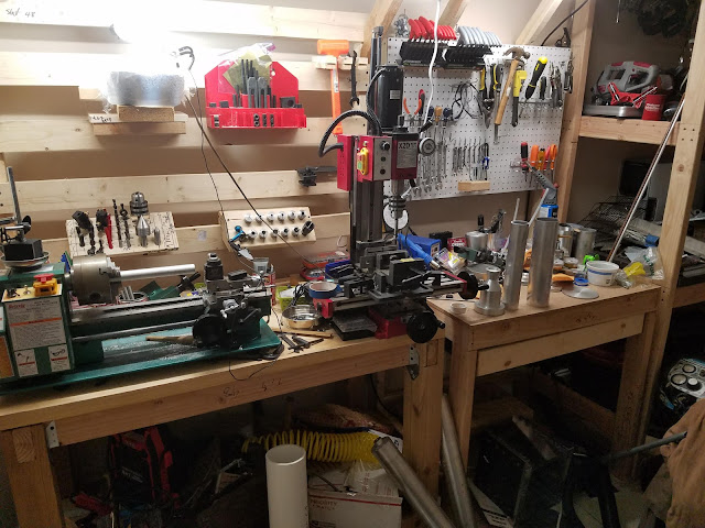
Been building one day and one dollar at a time. Infrastructure is my new game. Couple grand in but still much to be done. Lathe and mill bought. Cylinders for brazing aluminum acquired. Materials ate in. Designs have been designed. My new rocket is going to be a 250lbf flyable model. It's a bit of a living mess for the time being but more to come.

Friday, January 13, 2017

Still at it!

Between work and life, time comes sparingly in waves. Yet, I grab hold of the loose straws of time that I get and forge progress! Sounds epic... if the follow up isn't 'yet very slowly'. More rockets are coming soon, hence I have saved enough for a milling machine, but here is some of what I have gotten done in the last year:
CNC Progress


Wall Mounted Computer


Lathe Upgrades


Smoker out of a 30 gallon water heater