
Monday, March 31, 2014
Sunday, March 30, 2014
CFD Simulations and Thermal Analysis
Being that my day job is a Computational Fluid Dynamics Engineer, it only made sense for me to do a simulation of my rocket. It is a 3D density based simulation with heat transfer through the walls conducted on a 1.2 million node grid on a 96 core, 768 GB ram simulation server.
In the inside of the thrust chamber the temperature is 5200 F and the coolant water is 70 degrees when it enters. You can see that the most important area is the throat of the rocket. I adjusted the range in the 3d image to be red at the temperature of boiling water. You can see that the coolant does not reach this temperature so we are in good shape there.
The next is a cross section of the aluminum in the throat. Here the melting temperature of aluminum is ~1200 F with a loss of most major material properties near 800 F. The coolant keeps the material in the throat region at a balmy 600 F which is perfect for the performance of the rocket.


Friday, March 28, 2014
Build day 15: Finally getting caught up
The last few parts are on order, hopefully they are the last so I have gotten some free time. Since my first rocket is turning out to look more like a Frankenstein rocket, I have reinvested my time and everything I've learned into version dos.
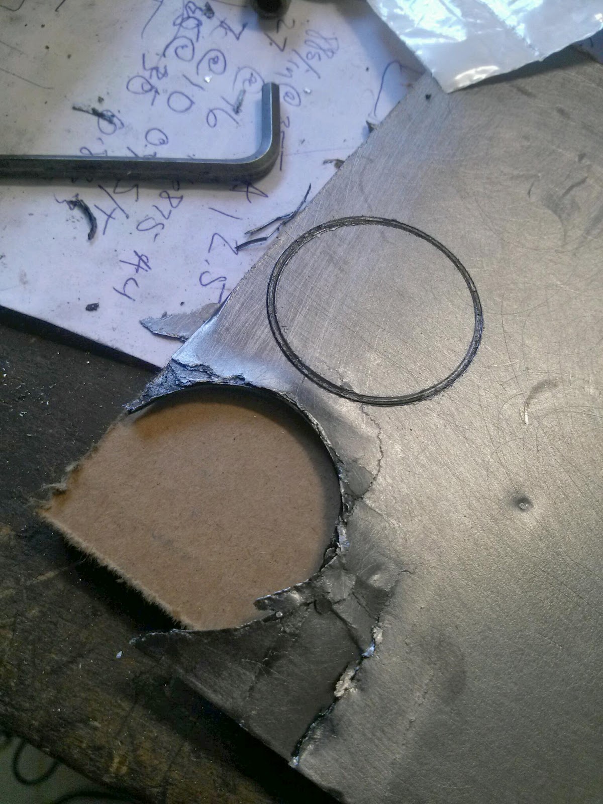
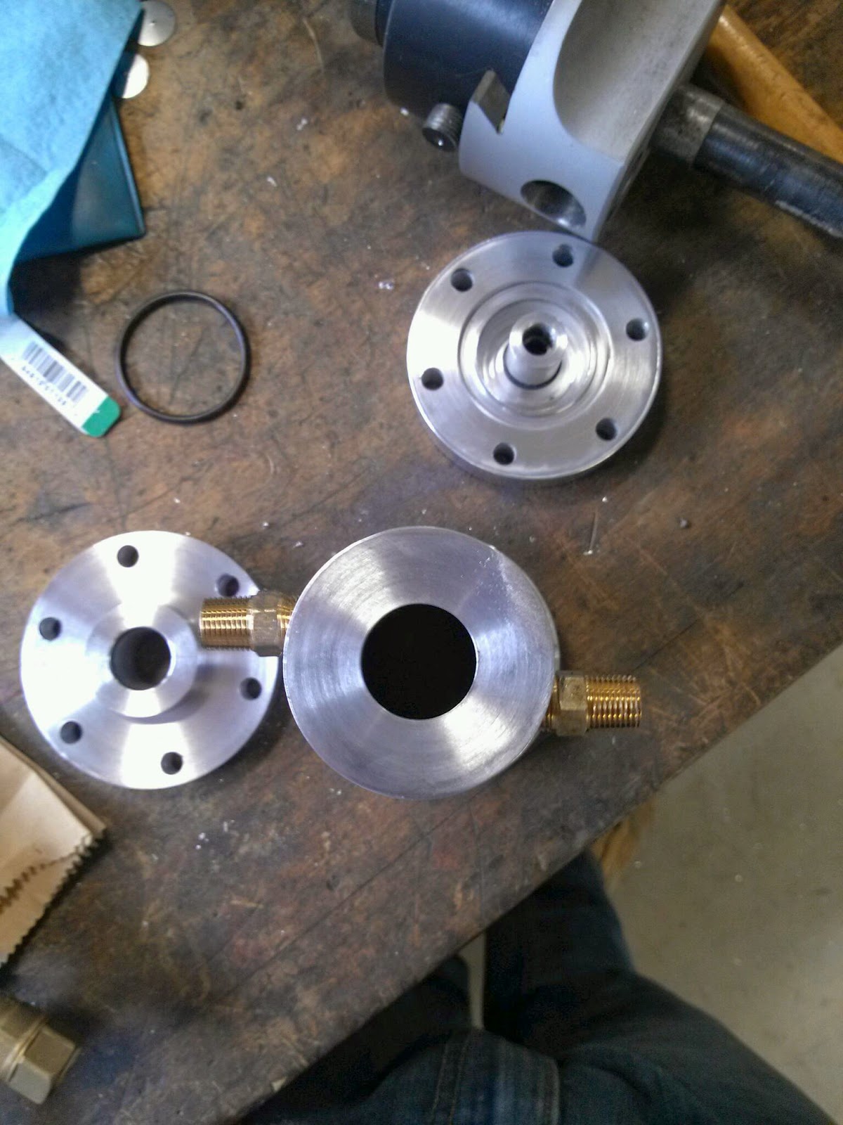
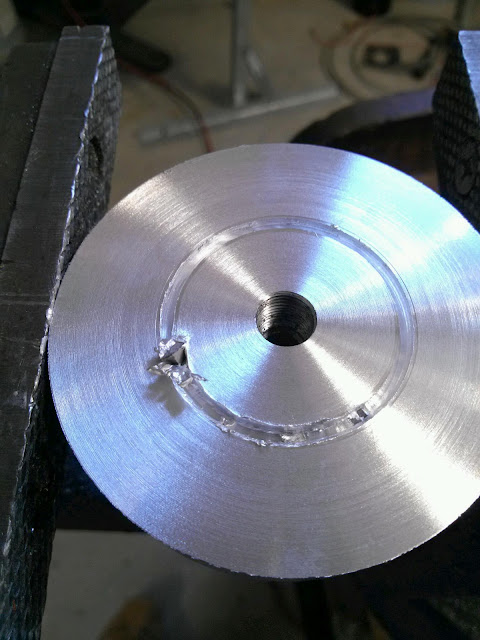
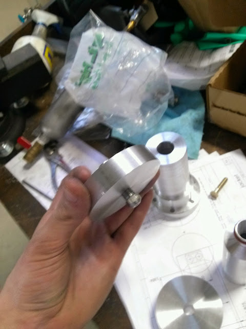
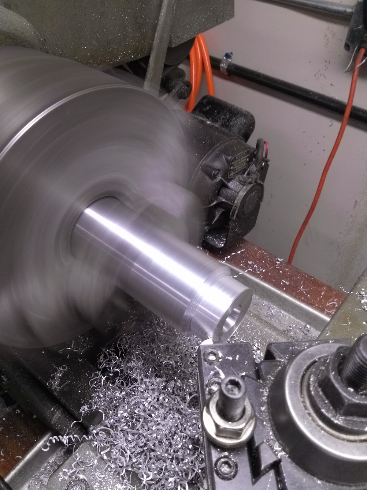
One thing I learned is that grafoil needs to stay in my nightmares where it belongs. There is no way that I would be able to cut it into the tiny washer shape that I need. I decided to lathe out the groove to the edge and make a big washers for it instead.
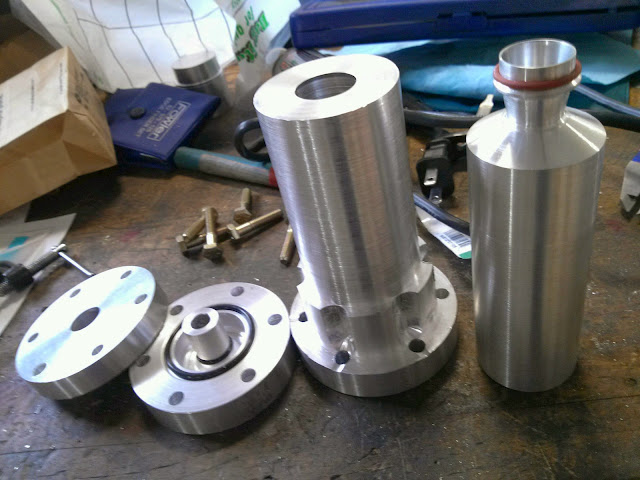
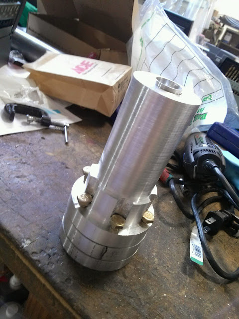
I decided to modify my design to fit standard gasket sizes, instead of the other way around. I only had to change things around 1/16th of an inch in any direction so it will be very worth the trouble. I also bought the materials to make this thing look pretty while being functional. All of my aluminum threads are starting to strip out so I will probably need to silicone them in for the time of the test. I will be remaking my rocket out of steel, except for the thrust chamber which will still be aluminum for it heat transfer properties. The injector plate will be made out of 316 stainless... or so I think. Steel has turned out to be a whole new monster and I haven't even touched the stainless yet! More to come soon!


One thing I learned is that grafoil needs to stay in my nightmares where it belongs. There is no way that I would be able to cut it into the tiny washer shape that I need. I decided to lathe out the groove to the edge and make a big washers for it instead.
I decided to modify my design to fit standard gasket sizes, instead of the other way around. I only had to change things around 1/16th of an inch in any direction so it will be very worth the trouble. I also bought the materials to make this thing look pretty while being functional. All of my aluminum threads are starting to strip out so I will probably need to silicone them in for the time of the test. I will be remaking my rocket out of steel, except for the thrust chamber which will still be aluminum for it heat transfer properties. The injector plate will be made out of 316 stainless... or so I think. Steel has turned out to be a whole new monster and I haven't even touched the stainless yet! More to come soon!


Monday, March 24, 2014
Build day 14: Fuel injector test
Not the best pictures cause I honestly didn't expect a monsoon out of this nozzle. 300 psi sprayed water at least 15 ft into the air. I can't believe the that this is only 1/10th of the total flow into a 1.4 inch pipe that I'm going to proceed to light on fire.


Friday, March 21, 2014


Wednesday, March 19, 2014
Build day 12: 3 hours of touch up
Got the jacket back from Geoff and of course its amazing. I just had to do a little grinding on the inside. I also made my stamp for the grafoil gaskets to seal the combustion chamber. Next stop is to get some seals ordered and go get some angle aluminum for the thrust stand

Friday, March 14, 2014
Build day 11: Channeling for the bolt heads , polishing, and making sure everything fits
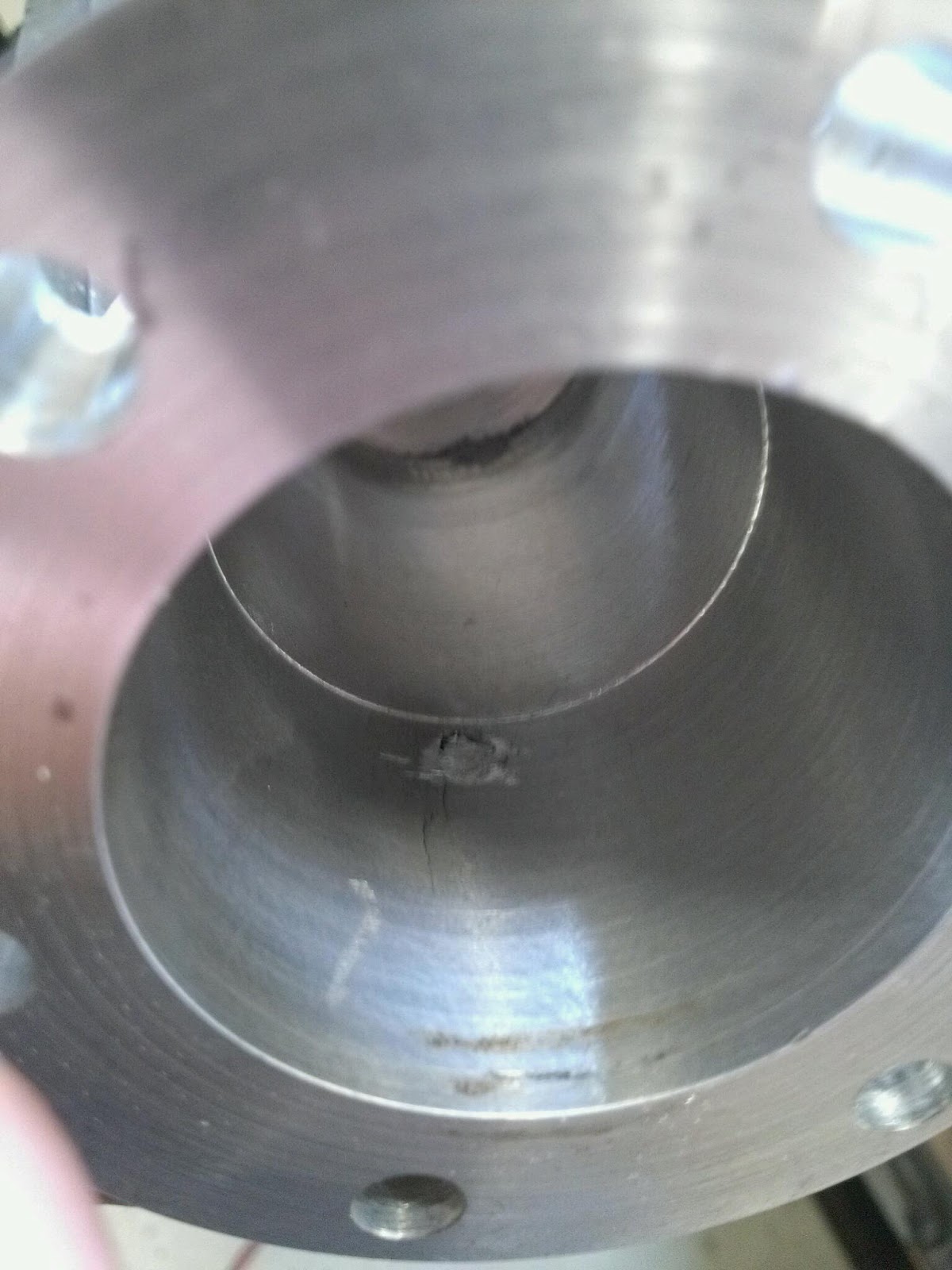
I cut out 5 of the 6 grooves of the bolts. On the last one, I finally understand all those old-tymers that ward again chinese-made stuff. My Chinese made tool holder wiggled itself loose and plunged the bit through the wall of my coolant jacket... TRAGEDY! I took it to the machinist at my work and showed off what I had done and what had happened, almost in tears, to which, he sighed but said "Ahh don't worry about it. Ill take it home over the weekend and fill the hole with weld. When you mill it, you won't even know it was there"
Thank God for Geoff Hollis. If he wasn't here with more years of machining experience than twice what I've been alive, this rocket wouldn't have made it this far. I think I'm going to name my rocket in his honor, the HolliStar rocket!
Total man hours put into machining the rocket up to this point: 41.5 hours


Thursday, March 13, 2014
Build Day 10: More bolt holes and making everything look pretty
Everything was going great until my bit caught and broke off. It tore into my injector face some but there is no way that I am going to remake the whole thing over this. Im just going to buff it out, put some extra grafoil in, and hope for the best. I can always remake it later.
I got the rest of the bolt holes drilled in all the plate and some how they miraculously fit. To get the bolts to sit flush, on the outer jacket flange, I am going to have to do some dremil work but nothing too big.
The next big step is going to be to get a steel wire steel and a buffing wheel to cover up all my tool marks.


Wednesday, March 12, 2014
Build day 9: More components and bolt circle try numero uno
Turns out I am going to need to buy that other fuel nozzle anyway because the filter on the back of the sprayer doesn't fit inside of my injector plate.


Tuesday, March 11, 2014
Build Day 8: Finishing the thrust chamber and starting on the main injector plate
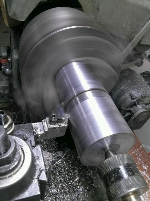
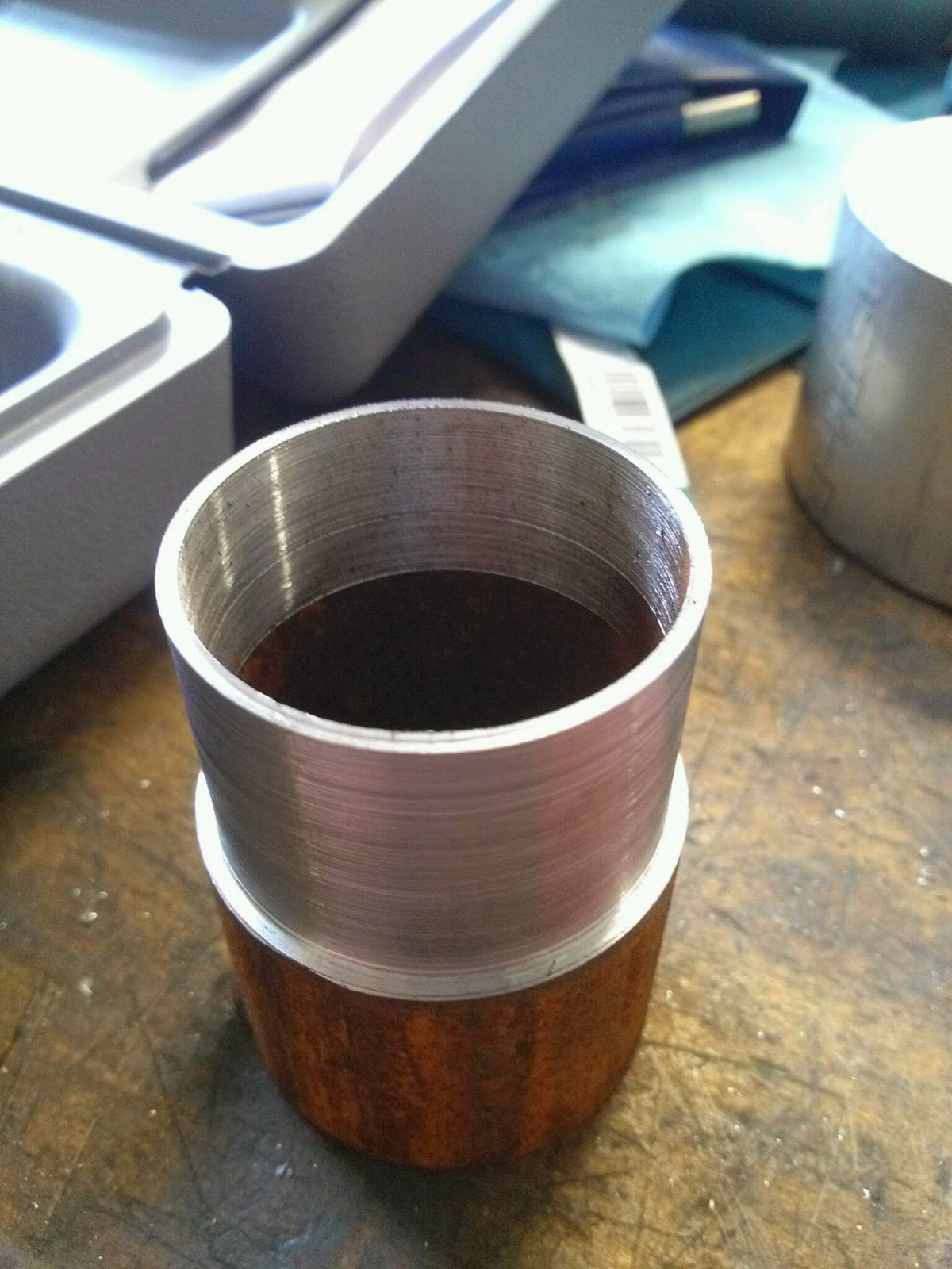
1/16th of an inch thick walls will certainly perform better than the 1/8th inch that I had originally planned but machining it was a different story. I was sweating that I was going to shear the chamber while I was cutting the outside down to the right thickness. 1/16th of an inch is about the width of a single letter on this page!


Viola! That thrust chamber is so thin it sounds like it is made of glass!

I swear it looked a lot bigger in my head! And on paper!


Perfect fit! The cooling channel checks out to the 10-15 thousands that I sized it for to keep the water from boiling in the jacket!

I still have to cut the 45 deg angle for the o-ring seat and the thickness of the o-ring is 70 thousandths which should reduce the 250 thousandths more near to the correct 125 thousandths of design. If it is a problem, I can always cut the o-ring groove a little deeper.

I got a start on the backside of the primary injector plate. Digging that groove is surprisingly difficult. Every bit screams!
Monday, March 10, 2014


Subscribe to:
Posts (Atom)